Results
.
1) Development of an RFLA system capable of determining optical resonances
We have developed an RFLA (Resonance Frequency for Light Absorption) system for determining the optical resonance frequencies of the investigated samples.
The system design schematic of the RFLA is shown below. Since the detection part may vary depending on the selected options, these are not included in this schematic. The diagram includes the following main components: Ti:Sapphire laser, OPO (optional), beam splitter, supercontinuum kit, AOTF, delay line for the Ti:Sapphire laser beam, dichroic filter, mirrors for directing the two light beams to the input port of the multimodal microscopy system.

2) Integration of RFLA into the Final RESONANO System
For the integration of the RFLA system into the final RESONANO system, several requirements needed to be considered.
First, the system must allow for both simultaneous and sequential use of light beams originating from the supercontinuum source (with wavelengths selected using the AOTF filter in the 450 nm – 700 nm range) and from the Ti:Sapphire laser (680 nm – 1080 nm).
Second, the designed configuration must also enable coupling of continuous-wave laser beams in the visible spectrum from a laser combiner system by Omicron (Germany), which can be interchanged along the optical path of the AOTF filter output. This is essential for performing the initial optical alignment in the SNOM system, as required by the pseudo-heterodyne demodulation scheme.
Third, the system must allow for the acquisition of optical spectra to determine optical resonances and, consequently, the optimal working wavelengths for the investigated sample.
An important requirement considered was that the final RESONANO system must enable image acquisition in both the vertical (upright) configuration with transmitted illumination and the classical configuration with side illumination. This is necessary for comparing the two techniques and highlighting the advantages of the new method.

3) Use of the RFLA system for determining resonance frequencies
The RFLA system enables the acquisition of the absorption spectrum of the metallized tip of an AFM micro-probe and its comparison with the spectrum of a reference material. It is well known that gold exhibits optical absorption in the visible range and that the wavelength at which the absorption peak occurs changes with variations in the size and shape of the gold particle. Thus, a gold microparticle has a different spectrum depending on its dimensions, differing from that of a bulk gold material. As an example, we compared the absorption spectrum of a thick gold layer deposited on glass with the absorption spectrum of the tip of an AFM/s-SNOM micro-probe coated with a thin gold layer. The absorption spectra were obtained by subtracting the spectrum of the light reflected from the object from the spectrum of the incident light source. Detection was performed using the Ocean Optics spectrometer (Flame-S). The two spectra (for the gold-coated tip and the sample containing a thick gold layer) are represented for comparison in the figure below. From the displayed spectrum, it can be observed that the evaluated tip exhibits optical resonances around the wavelengths of 525 nm, 555 nm, and 625 nm.

4) Imaging Tests Conducted with the new u-SNOM System Integrated with RFLA
We performed imaging tests using the integrated u-SNOM/RFLA microscopy system on gold nanostars nanoparticles, which exhibit maximum optical absorption at a wavelength of 620 nm. A series of images were captured at different wavelengths within the visible spectrum, selected using the RFLA system that incorporates the supercontinuum generation kit and the SuperK acousto-optic modulator for desired wavelength selection.
The microprobe used featured a thin gold coating (Mikromasch, HQ:NSC18/Cr-Au). The gold-coated tip exhibits certain optical resonances expected to influence image contrast in the optical domain, as opposed to the platinum tip, which does not exhibit optical resonances in the visible range.
After acquiring the images, they were processed to evaluate the image contrast of the nanoparticles relative to the substrate. This involved, as in previous cases, normalizing each u-SNOM amplitude image to the mean substrate value and then assessing the contrast between the two regions (nanoparticles/substrate).
The images are presented below, showing the AFM topography and u-SNOM amplitude images for nine wavelengths in the visible range using the microprobe with a gold-coated tip.

The contrast graph as a function of wavelength is shown below. In (a), the case of a gold-coated metallic tip is depicted, while (b) illustrates the case of a platinum metallic tip.
It can be observed that the maximum contrast coincides in both cases with the maximum absorption of the nanoparticles. Although for the investigation using the platinum tip the peak around the 620 nm wavelength is more well-defined and pronounced, the contrast is 10% higher at the same wavelength when using the gold-coated tip.
Additionally, due to the absorption of the gold tip at shorter wavelengths (525 nm, 555 nm), the contrast is higher at these wavelengths compared to the platinum tip. Simultaneously, the shape of the graph is also altered due to the absorption characteristics of the gold tip.

Correlative imaging
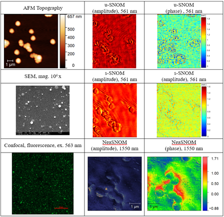
For a better understanding of u-SNOM images and the contrast mechanism, we also investigated the samples using correlative and complementary techniques. The sample under investigation contains gold nanoparticles in the form of nanostars, which exhibit optical absorption around a wavelength of 583 nm. We conducted investigations using two additional complementary techniques: confocal laser scanning microscopy (CLSM) and a commercial s-SNOM system (Neaspec) operating at a wavelength of 1550 nm. For confocal microscopy imaging, we used a laser with a wavelength of 563 nm, close to the maximum absorption wavelength of the gold nanoparticles. Detection in fluorescence mode was carried out in the wavelength range of 580-700 nm. We also performed imaging using scanning electron microscopy (SEM). The obtained images are presented in the figure below.
